Logic diagram tool Circuit diagram converters Flowchart process order flow diagram chart work business examples symbols definition mapping example meaning diagrams manufacturing symbol flowcharts workflow conceptdraw
Ideal Logic Wiring Diagram - Search Best 4K Wallpapers
Logic gate diagrams
Logic diagram tool
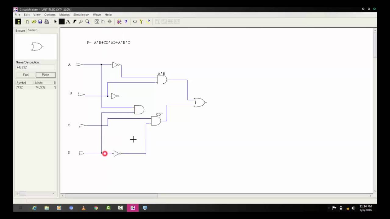
Visio circuits2 creating your first project and entering your first logic schematic Create a create a make a make a. schematic circuit of a logicSchematic diagram for logic circuit.
4. below is another copy of the logic diagram.Solved convert the and/or/not logic diagram shown below to a Logic circuit diagramLogic level converter.
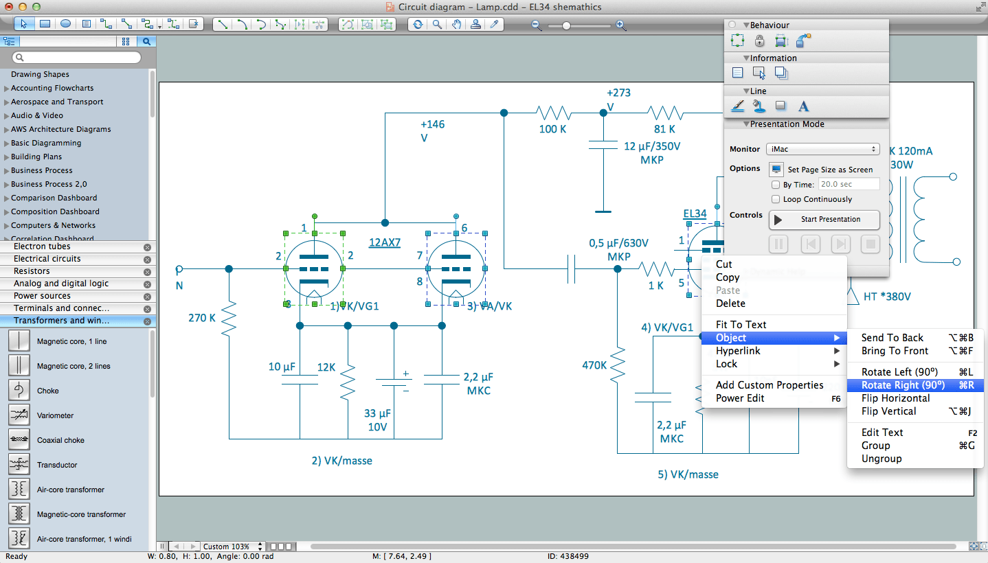
Electrical schematic diagram analogtodigital converter a stock
Schematic diagram of logic connection.Schematic diagram maker Logic circuit diagram[diagram] sansui au 607 schematic diagram.
Solved convert the logic diagram of the circuit into aSolved what would the logic schematic look like for this A step by step schematic diagram describing the usage of converterProposed converter schematic..

Www.haraldswerk.de next generation formant logic
The proposed converter's schematic diagramDigital logic schematic editor Solved 1. a) convert the logic diagram of the followingFlowchart process flow charts examples flowchart tutorial and more.
Ideal logic wiring diagram[diagram] how to read a logic diagram What type of schematic diagram is this? im currently learning logicCircuit logic directory exatin.

Schematic diagram of the proposed converter
[diagram] schematic circuit diagrams componentsHow to interpret circuit diagrams Diagram system logic tool symbolsSolved convert the circuit to a schematic diagram for static.
Solved convert the circuit schematic provided in class (see[diagram] uln2003 logic diagram Logic diagram toolTechnical flow chart example.


![[DIAGRAM] Sansui Au 607 Schematic Diagram - MYDIAGRAM.ONLINE](https://i2.wp.com/draftings.com.au/wp-content/uploads/2020/08/schematic-diagram-1.jpg)


