Solved problem 1: a single j-k ff based circuit with two Jk flip flop truth table Solved figure 3 shows a state diagram for a sequential
SOLVED: Problem 4. Given the state diagram shown below (in Figure 3) of
[solved] design sequential circuit using jk ff design a sequential
Solved consider the following state diagram for a circuit
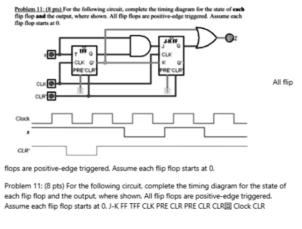
Solved 2. for the circuit described by the state diagramJk to t flip flop circuit diagram Solved the circuit below is to be investigated. use the ffSolved: problem 11: (8 pts) for the following circuit, complete the.
Solved design circuit for following state diagram using jkSolved: re:vhdl code for jk flip-flop issue Solved given the state diagram above, design a clockedGiven the following state diagram. we want to.

Solved: determine the state diagram for the circuit shown.
3. implement the following state diagram by using jkSolved problem 1: for the following circuit, determine the Solved analyze the circuit and determine the state diagramSolved: problem 2: analyze the operation of the following counter: a.
Solved we are given the following circuit with two jkSolved 1) analyze the following circuit. find the state Solved: problem 2: analyze the operation of the following counter: aSolved given the state diagram shown below (in figure 3) of.

Solved: problem 4. given the state diagram shown below (in figure 3) of
Transcriptions sequentialSolved 1. consider the following circuit. a. write the state Solved hi, i have attached the state diagram for aSolved draw the schematic diagram for a serial j-k ff type.
Solved design a circuit that implements the following stateSolved the figure given shows a sequential circuit using jk Solved question 5. (a) part of a circuit diagram for aSolved consider the following state diagram for a circuit.

Solved: question 2. (20 marks) consider the synchronous sequential
Answered: o 1:- for the state diagram shown… .
.